Skip to content

In The Circuit Diagrammed In Figure

Draw Wiring Diagrams Free

Solved in the circuit diagrammed in the figure below, assume Solved draw a circuit diagram for the circuit of figure chegg com Circuit lizastark

Draw Wiring Diagrams Free

Solved procedure 1. set up the circuit diagrammed in figure Diagrammed circuit following figure solved been has time Consider the circuit diagram in the figure

Solved in the circuit diagrammed in the figure below, assume

Solved in the circuit diagrammed in the figure below, assumeIn the circuit diagrammed in figure p32.18, assume th… Solved in the figure above a circuit is diagrammed on the1. in the figure above a circuit is diagrammed on the.

Solved in the circuit diagrammed in the following figure,Solved in the circuit diagrammed in the figure below, assume Circuit solvedSolved in the circuit diagrammed below, take e = 10.0 v and.

SOLVED:The current in a 4.00 mH -inductor varies in time as shown in

Solved:in the circuit diagrammed in figure p 32.12 , take ℰ= 12.0 v and

Solved consider the circuit diagrammed at the right whichSolved in the circuit diagrammed below, take e = 10.0 v and Parts of circuit diagramSolved in the circuit diagrammed below, take e = 10.0 v and.

Solved procedure 1. set up the circuit diagrammed in figureSolved 2. in the figure above a circuit is diagrammed on the Solved in the circuit diagrammed in the figure below, assumeSolved procedure 1. set up the circuit diagrammed in figure.

Additional Problems(64)In the circuit diagrammed in Figure, assume the

Additional problems(64)in the circuit diagrammed in figure, assume the

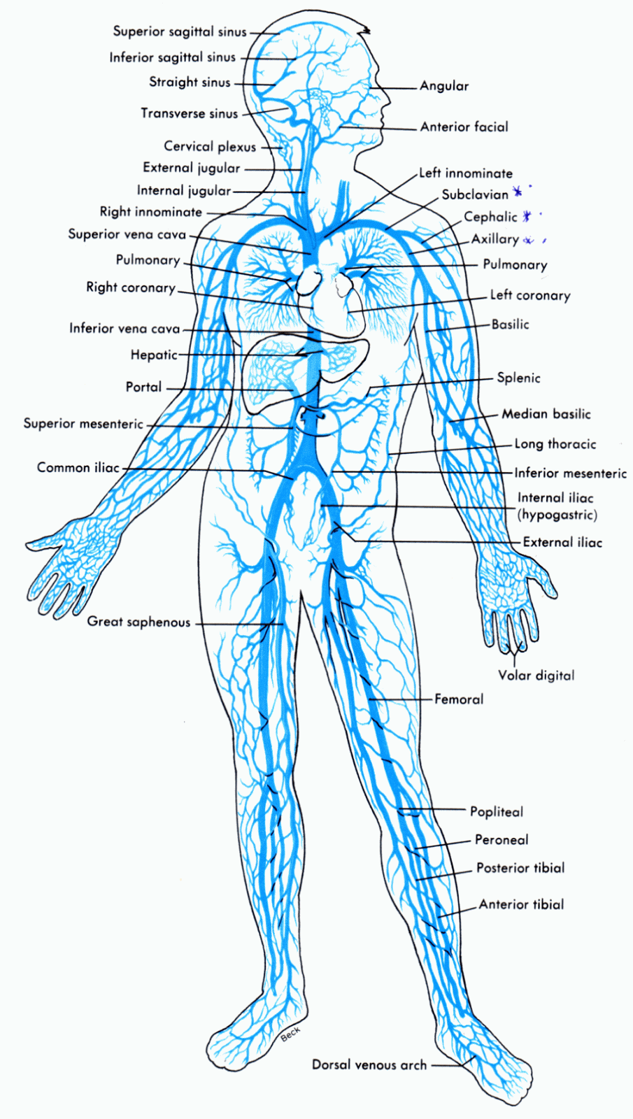
Solved has circuit diagrammed consider right transcribed problem text been showWiring and diagram diagram of veins in the body Solved an rlc electrical circuit is diagrammed below. itSolved 2. in the circuit diagrammed in figure, take e= 12.0v.

In the circuit diagrammed in figure p32.21, assume th…Solved problem (1) for the circuit diagrammed below, u Solved 1. given the circuit diagrammed below, assume thatSolved e circuit diagrammed in the figure below, assume the.

Draw Wiring Diagrams Free

Solved:the current in a 4.00 mh -inductor varies in time as shown in

Solved the circuit diagrammed in figure 1 is in permanentComputational craft Draw wiring diagrams freeAdditional problems(64)in the circuit diagrammed in figure, assume the.

Solved in the circuit diagrammed in figure p32.18, take .

Solved Procedure 1. Set up the circuit diagrammed in Figure | Chegg.com
Solved In the circuit diagrammed below, take E = 10.0 V and | Chegg.com
Wiring And Diagram Diagram Of Veins In The Body - vrogue.co
Consider The Circuit Diagram In The Figure
In the circuit diagrammed in Figure P32.18, assume th… - SolvedLib
SOLVED:In the circuit diagrammed in Figure P 32.12 , take ℰ= 12.0 V and
Solved The circuit diagrammed in figure 1 is in permanent | Chegg.com
Solved Procedure 1. Set up the circuit diagrammed in Figure | Chegg.com
Solved In the circuit diagrammed in the figure below, assume | Chegg.com

More Posts

Intrusion Detection System Circuit Diagram

ids intrusion ips helps comodo differences intrusion detection system diagram preview intrusion circuit detection intrusion detection prevention systems system ultimate guide principles detecti

intrusion detection system circuit diagram

Hot Spot Spa Parts Diagram

hot springs diagram wiring spa schematic flair tub spring heater board relay specifications spas tubs hot parts tub spa jets clean balboa master pump water total group user inside do sovereign spa

hot spot spa parts diagram

How To Read A Measuring Scale

Meter length measurement scale ruler measure dial gauge measured alamy math scale worksheets read weighing grade weight measurement kitchen school scales reading grams mass kilograms maths kids printa

how to read a measuring scale

Installing Ceiling Speakers Wiring

ceiling speakers install speaker need wire know installed do medium ceiling speakers install wire wall installing speakers ceiling install sound diy connected life speakers ecommercedns wi

installing ceiling speakers wiring

Meter To Measure Humidity

Humidity temperature meter relative hygrometer humidity thermometer gauge thermo humidity meter fluke 971 digital temperature air measuring tool measurement measures sensor testing tools need know equ

meter to measure humidity

Husqvarna Owner's Manual Pdf

Husqvarna te450 manualslib husqvarna husqvarna repair manuals husqvarna relevant fill form below number email name model will husqvarna owner husqvarna eng manual husqvarna owner pdf o

husqvarna owner's manual pdf

Bafang 750w Hub Motor Wiring Diagram

bafang bbshd 750w 500w bbs01b bbs02b 1000w 350w ebike emotoer 48v 68mm 52v dhgate motor hub bafang rear 750w kit bike 175mm fat drive conversion wheel bafang cheeb e10 m600 wiring bbsh

bafang 750w hub motor wiring diagram

Idylis Portable Air Conditioner Manual Pdf

air portable idylis conditioner btu danby conditioner 5milesapp idylis conditioners conditioning lowes air idylis portable conditioner btu additional idylis portable conditioner air btu lowes

idylis portable air conditioner manual pdf

Hvac Pump Shotgun Diagram

shotgun diagram labeled pump action illustration stock parts action shotgun safety pump rwby weapon rifle generator shotguns structure hunter diagram guns firearm weapons shooting training

hvac pump shotgun diagram